Abbot Thayer’s Rock Garden
An image essay on trans-optic unrendering
Parallax experiment 2
An image essay on trans-optic unrendering
Parallax experiment 2

de-naturing
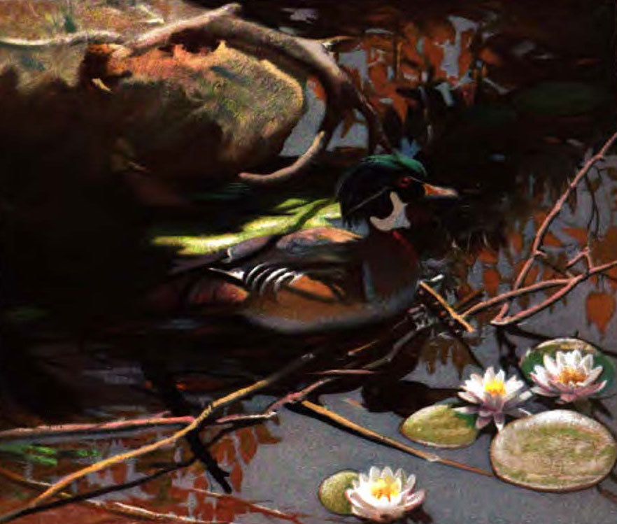
It starts with an ominous photograph containing an “ungrounded body”. The photograph was taken by Abbot Thayer in the first decade of the 20th century and depicts two wooden ducks. The fact that the second duck, supposedly to the right of the very visible duck, isn’t visible at all goes to prove Abbot Thayer’s theory of countershading. Countershading, also known as Thayer’s Law, is the tendency in animal coloration to be darker on the upper side and lighter on the underside of the body. In effect, this means that these animals counterbalance self-shadowing in a top lit environment - as most environments typically are. The wooden duck on the right, as opposed to the one on the left, follows this law and thus appears flat.
Abbot Thayer, as an artist with an eye trained towards naturalist representation, discovered the principle of countershading: the tendency of animals to reverse their environment’s lighting conditions. As well as countershading, he called this tendency sky-picturing or sometimes de-naturing. Abbot Thayer published his theories in “Concealing Coloration in the Animal Kingdom” and illustrated this concealing coloration with plates which he called “scientific paintings”.

trans-optics
In Abbot Thayer’s trans-optic Rock Garden, this notion of de-naturing, an evolutionary entanglement of the object and its environment are extended towards notion of making as well, shifting between different modes of optic and cross-contaminating mappings, simulations and projections.
prototypes
The project works through a series of object-prototypes, each of which could be understood as a projection surface for a series of questions about entangled optics. They start with the idea of un-rendering, a term I use to describe a digitally accelerated simulation and fabrication of Thayer’s law of evolutionary countershading. In short, it involves the etching onto an object a of the negative image of a its digital rendering. It involves a series of steps.
replica
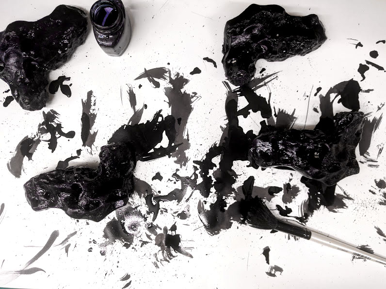
A series of plaster copies of the original is made. These are coated in a thin film of chinese ink.
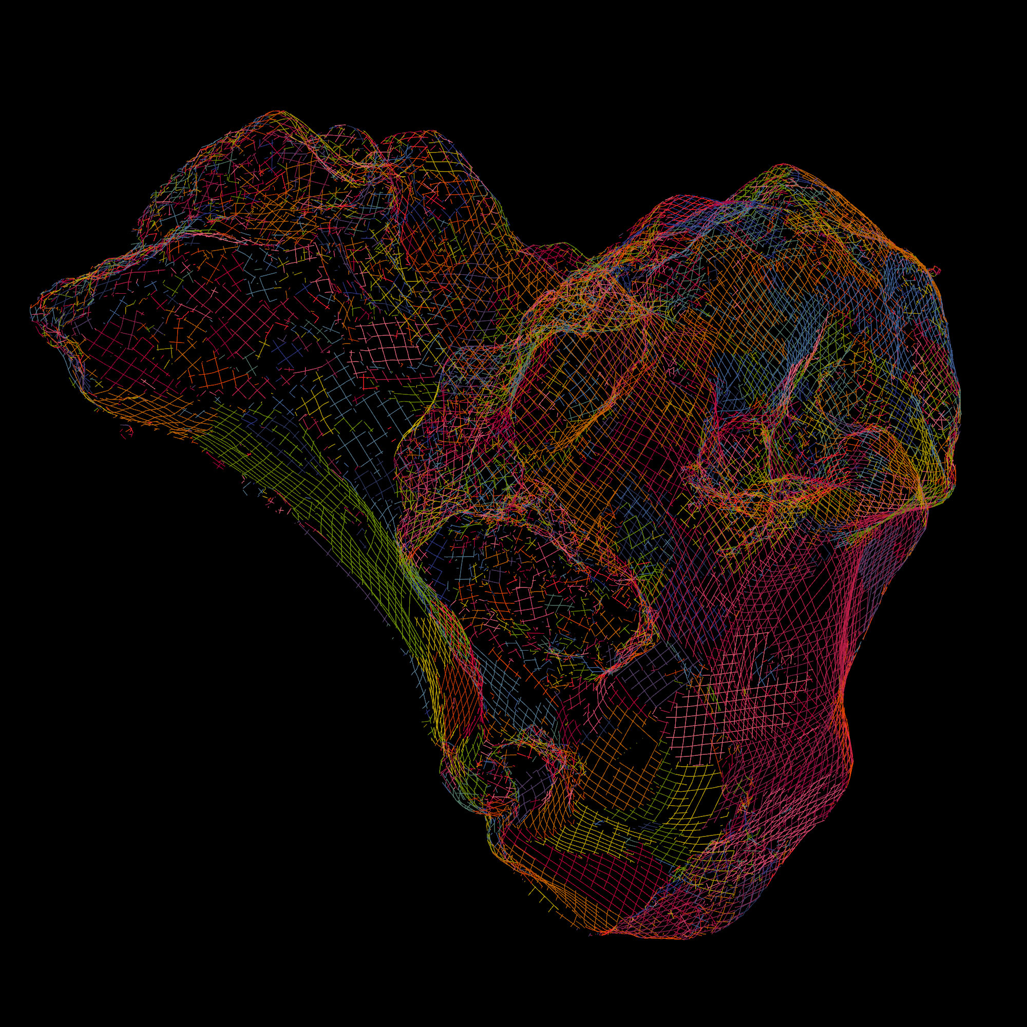
digitize
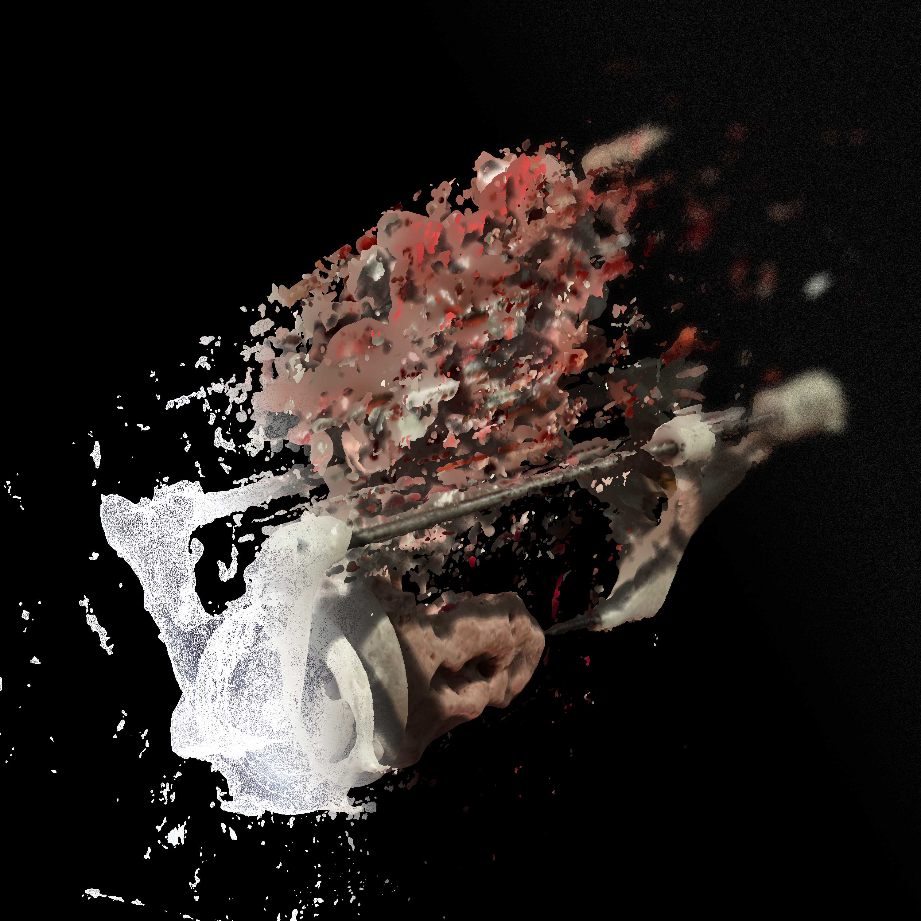
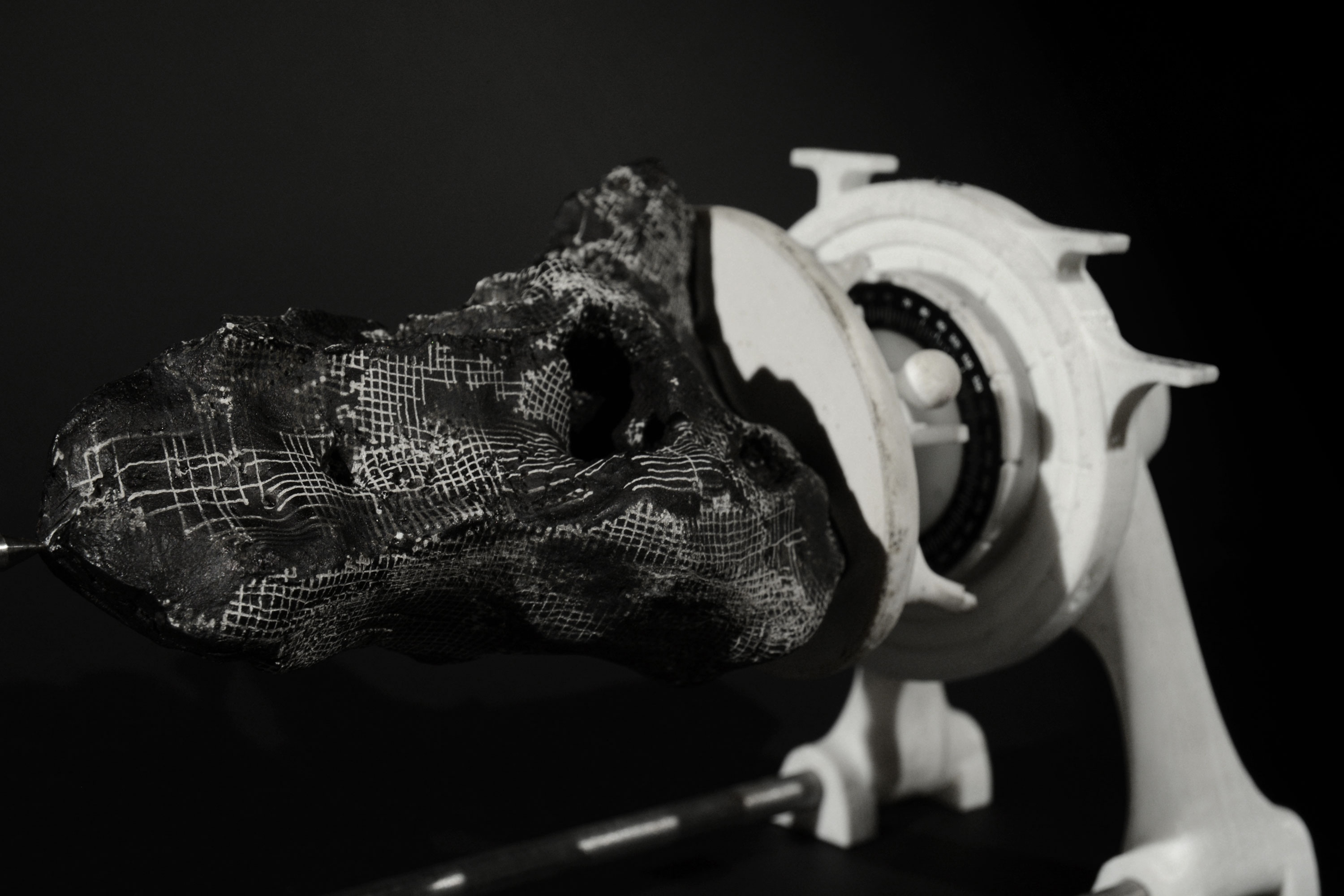
A digital copy of these objects is made using photogrammetry. For this, the object is is embedded in the instrumentation - which will later reappear as a part of the fabrication process - so it is referenced and scaled correctly.
virtual optics
A virtual ray-tracing rendering engine is used to simulate the lighting effects of a lighting environment on the digitized object.
un-rendering
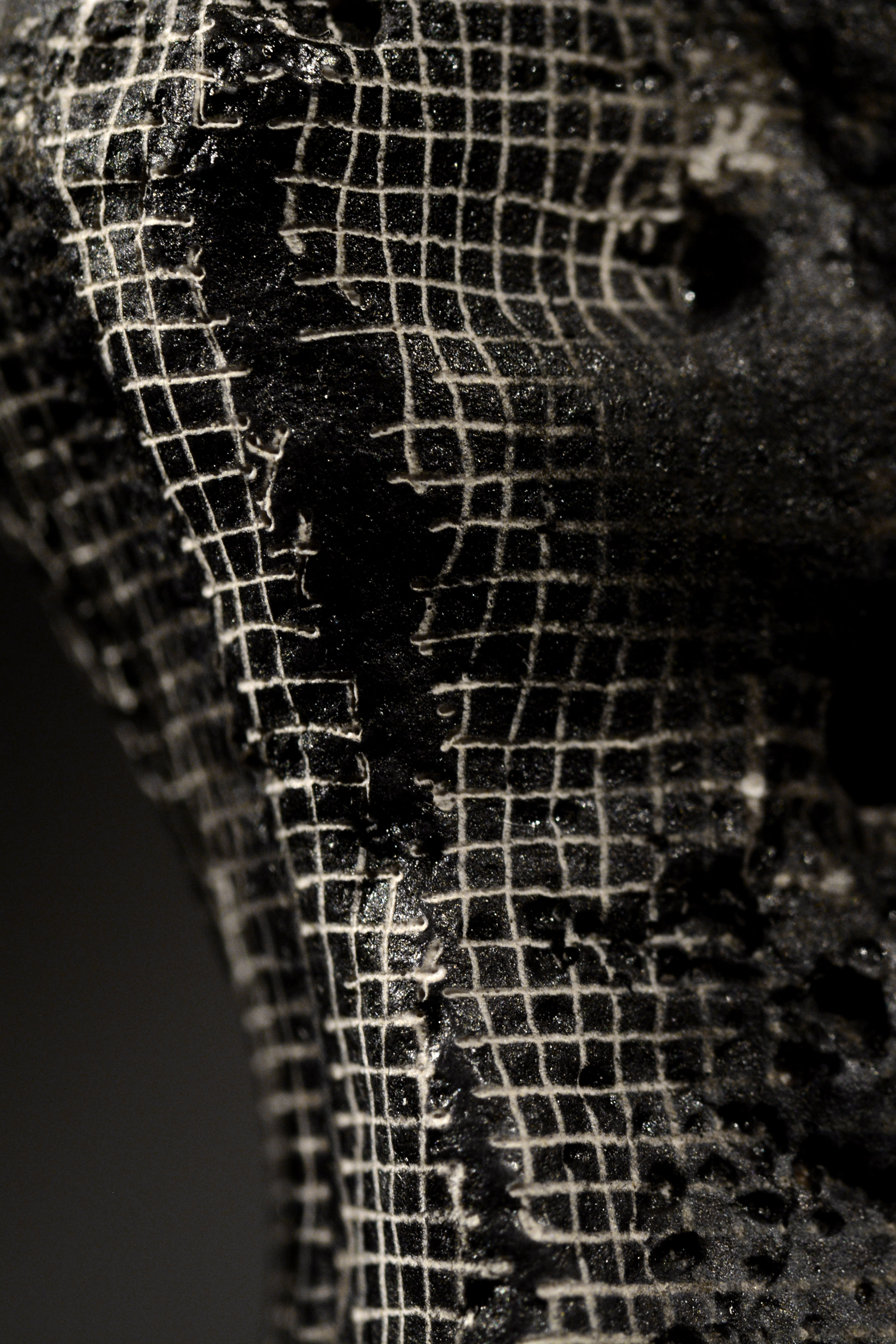
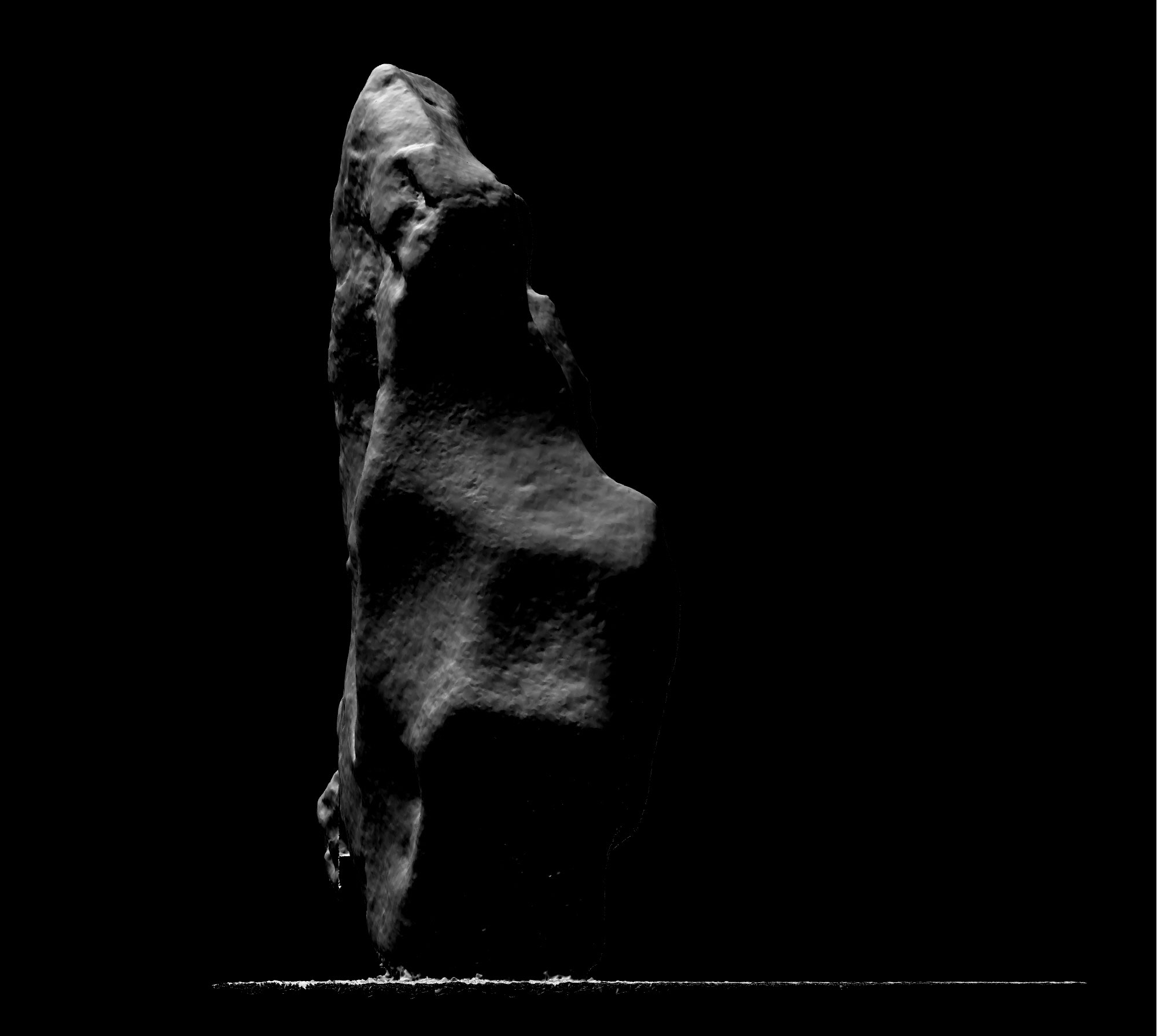
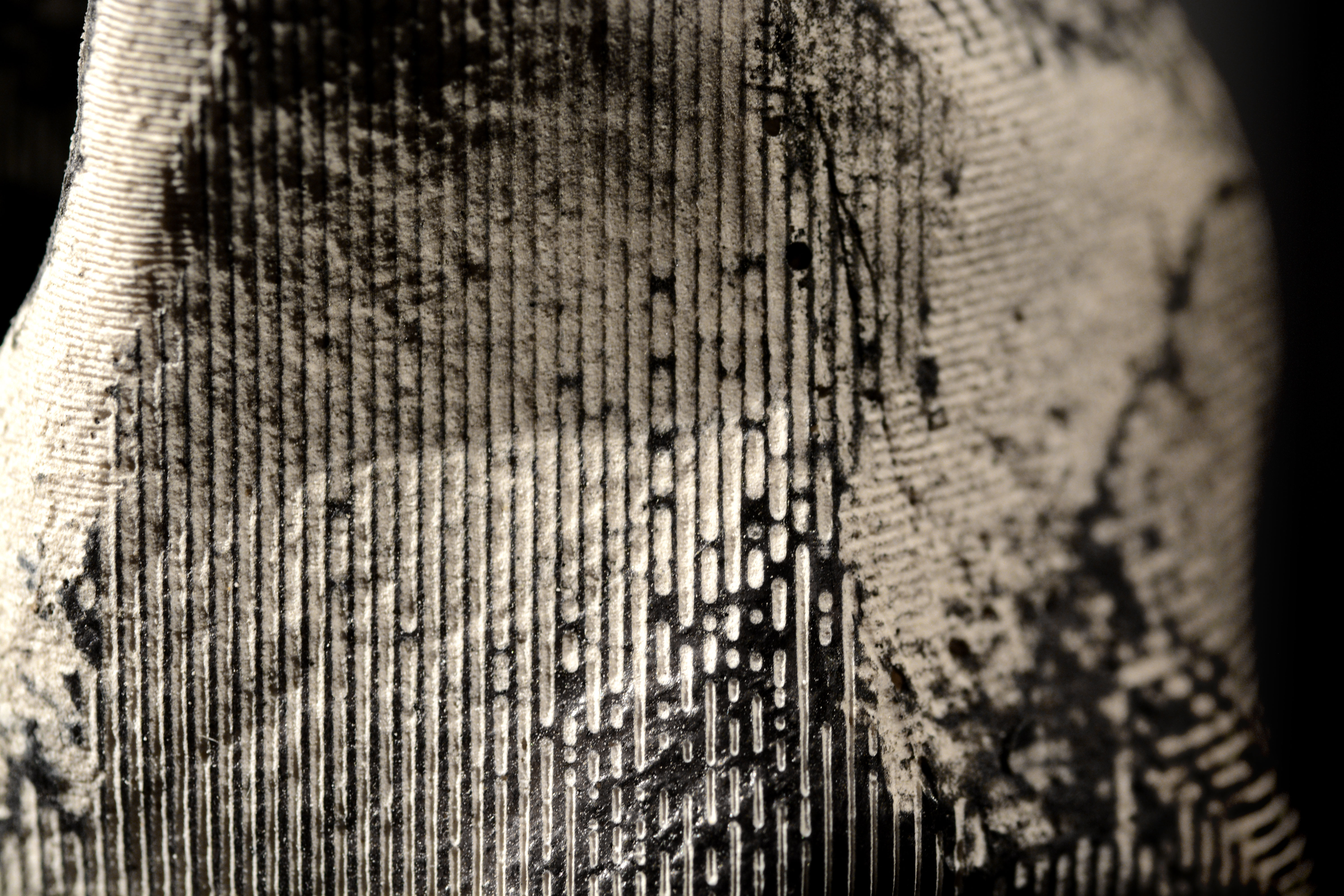
The aim then is to physically apply this simulation to the original object. This is done by selectively etching away the top coat of black ink with a laser cutter.
sgraffito
Usually, laser etching engraves/burns the image into a material so that dark zones in the image are burnt, white zones are left untouched. My digital sgraffito etching process reverses this logic: a black spot in the image will be engraved onto the object so that it reveals the white plaster underneath the layer of ink, so that effectively, a negative of the input image is created.
accelerated
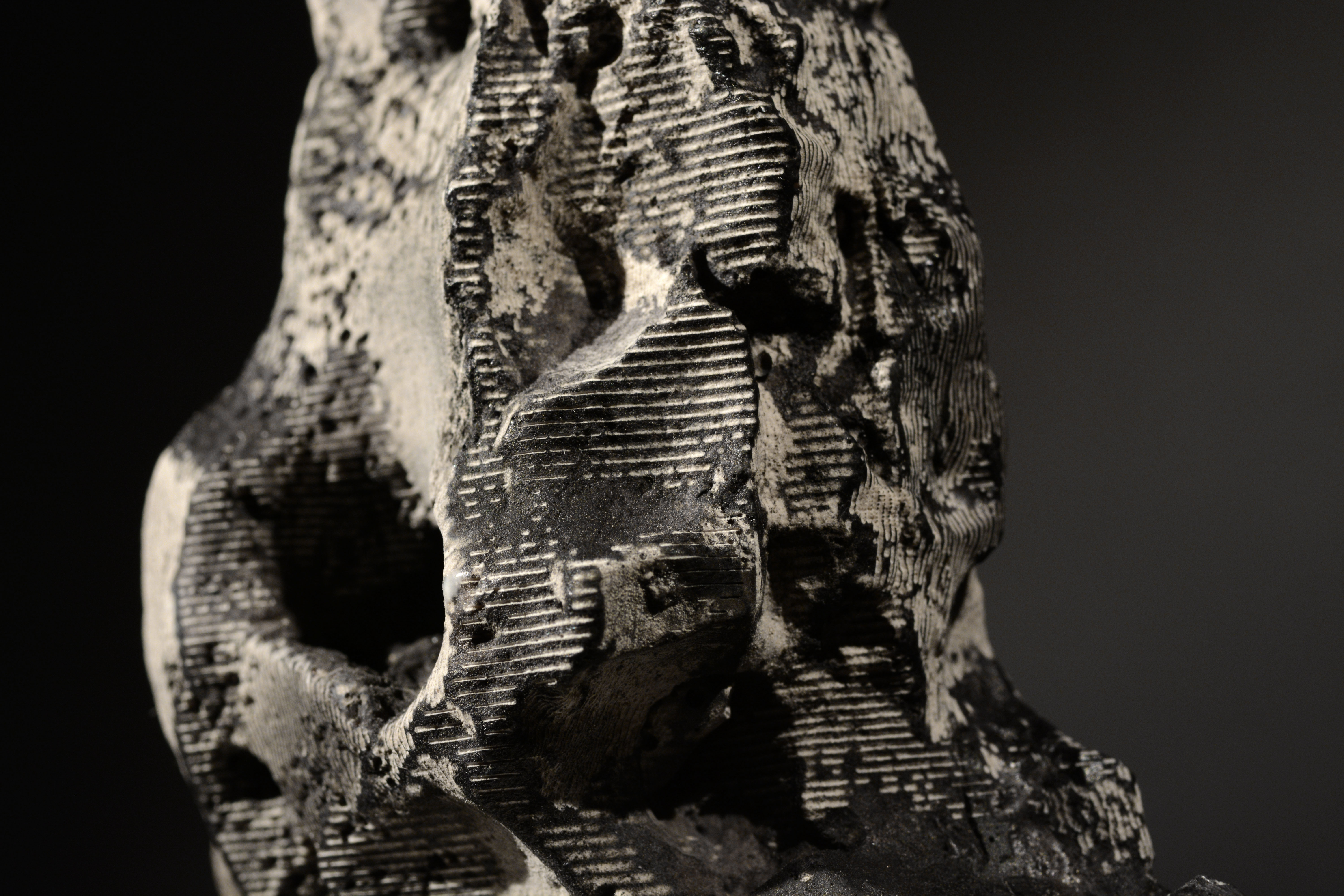
In other words, where the object has been virtually rendered bright, it gets physically un-rendered dark, and vice versa. This process of un-rendering is in effect a digitally enhanced acceleration of evolutionary countershading. In theory, this would mean that the colour of the object obliterates the shading it receives from its environment and the object should look entirely flat.
virtual environment
In a first phase, the environment in which the object is rendered is created purely digitally by placing virtual light-emitters.
captured environment
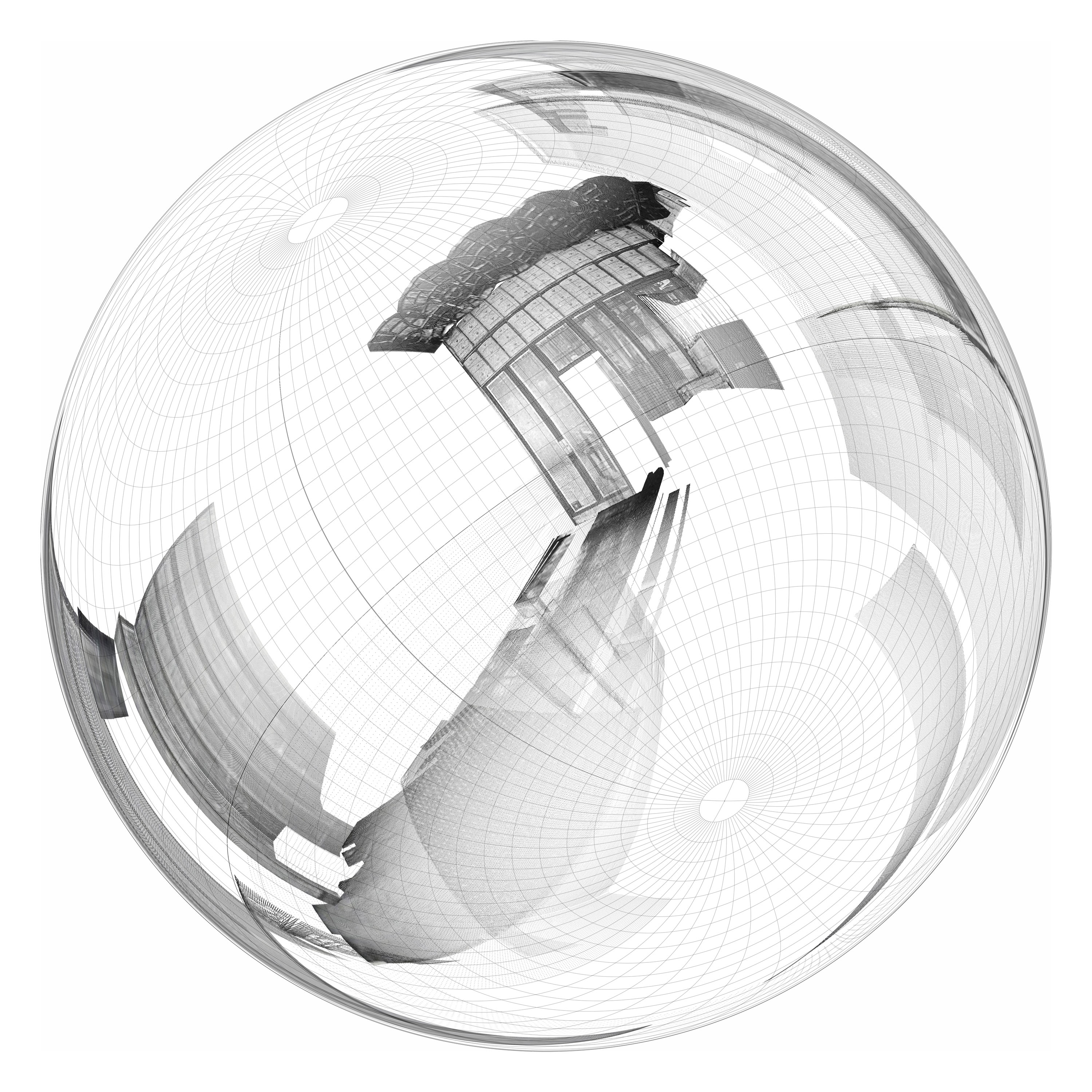
In a second phase, real-life environments are captured and are a used to virtually light the object. The environments are captured as light-probes using mirrored sphere, a technique often used in photorealistic rendering. The centre of this sphere then coincides with the virtual placement of the object.
reconstructed environment
In a third phase, the realisation that objects can be un-rendered in captured environments leads to the realisation that this can also be applied to re-constructed environments. A light probe in the reconstructed Goldman & Salatsch shop remaps all points in the parallactic cloud around a point of choice - an additional, virtual mirror around a weightless point. The light probe’s shadow zones aren’t as much created by interference of the viewer, who is exiled into a dimensionless point, or the mirror, which is weightless and cannot obscure, but by the shadows of the original 1901 images.
quasi-panoramic
A photograph of the mirrored ball is called a light probe and captures a panoramic image of the surrounding scene as seen from the virtual point at the centre of this sphere. To be more precise, these light probes are quasi-panoramic. These mirrored balls have two blind spots: the shadow behind the actual mirrored sphere and the part of the scene behind the photographer. Both the instrumentation of capture and the person who captures interfere with the very process of capture.
weightless
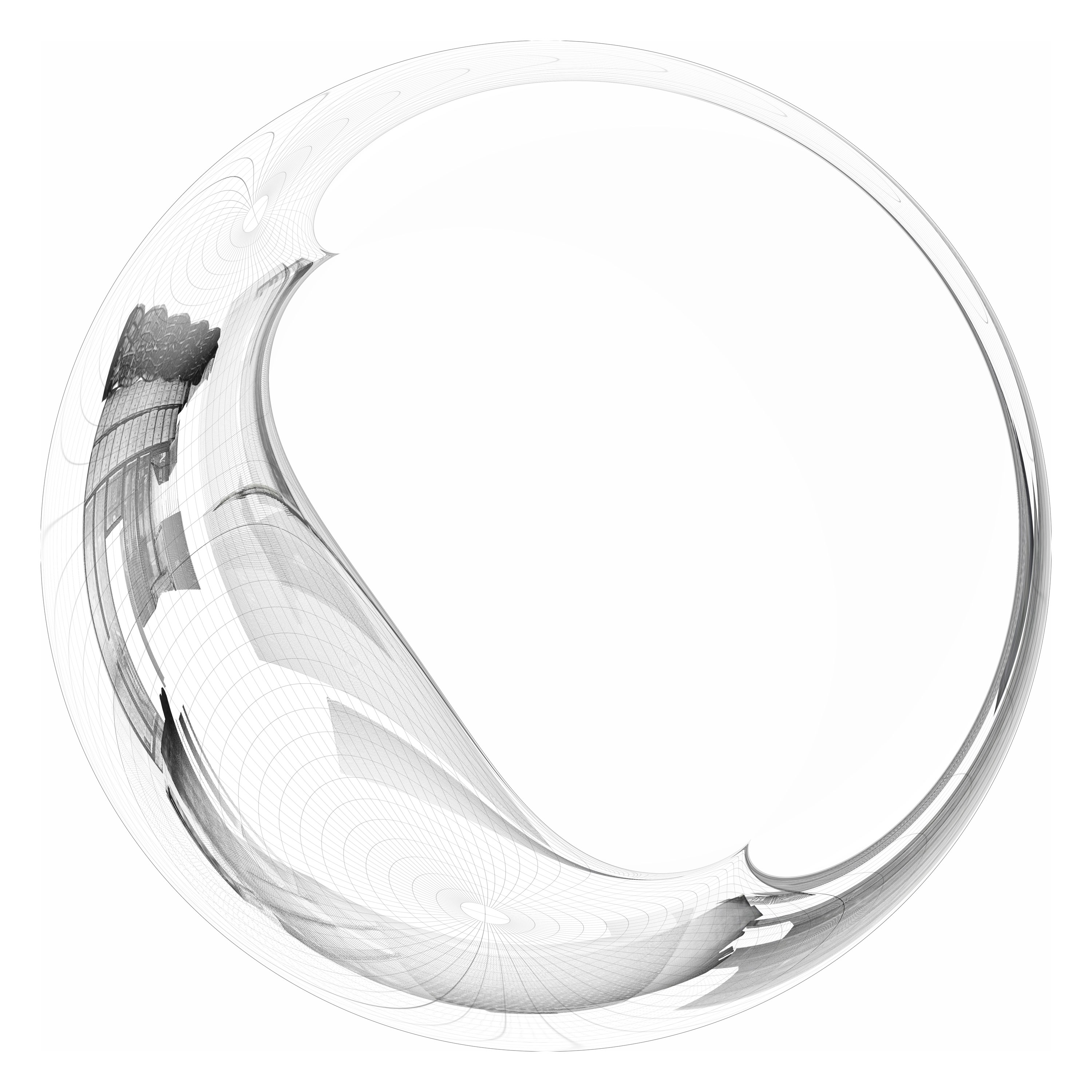
The cloud of points, wanders weightlessly, effortlessly without the fear of compression or warping, from its original cartesian position into its panoramic mappings and in between different panoramic mappings.
cannibal
With equal ease does it slip deeper into mappings – for example a light probe mapping of a light probe mapping, the drawing surrounding the original mapping now eating into the light probe, or rather the light probe swallowing its background environment.
weight
In the process of un-rendering, when the virtual objects are engraved back onto the physical object, the images literally gain weight again.
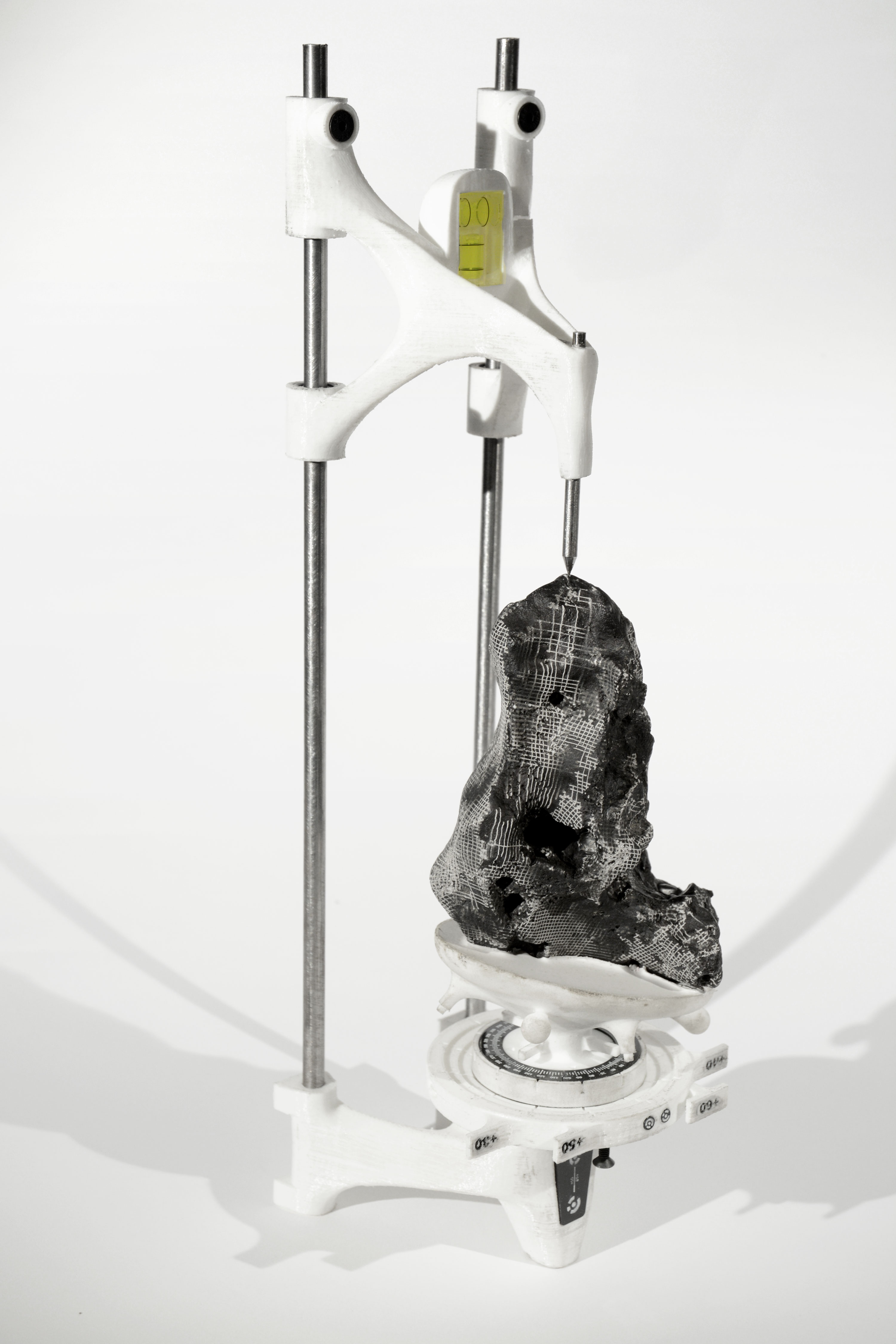
instrumentation
To access the object from multiple directions, a bespoke dividing head creates a third, rotational axis for laser cut engraving.
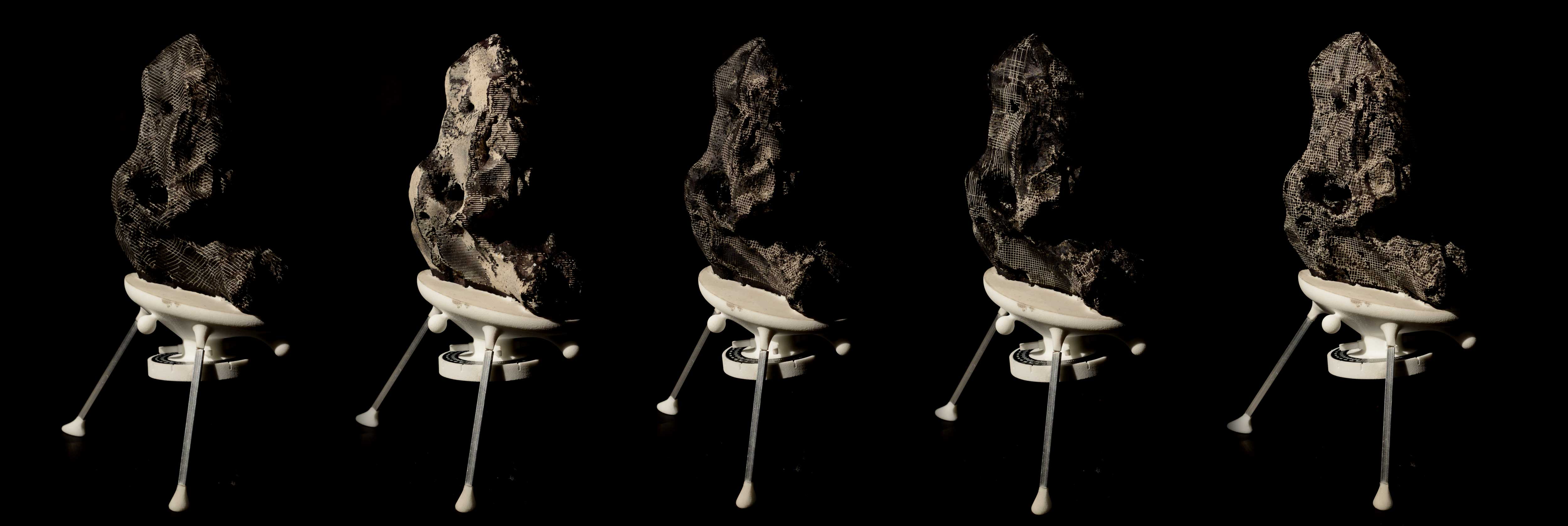
thayer divider
The dividing head, the Thayer Divider, is calibrated to register at rotational increments, for example each 60 degrees.

angles of incidence
This instrument creates a new mapping, the Thayer mapping, a purely orthogonal projection.
thayer mapping
The mapping assigns mesh vertices to a rotational orientation, a process which is automated by analysing exposure and angle of incidence
parallel
The orthogonal renderings are subdivided and projected orthogonally onto the object.
macro
The mapping is informed by the way the machine sees things. Light travels perfectly parallel at a macro scale due to the mechanics of the laser cutter.
focal depth
At a micro scale however, the laser does not travel parallel, it moves in and out of focus depending on the depth of the object.
focal stack
These planar maps, these parallel projetions hence also need to be separated according to the focal range of the laser: the focal z-height is incrementally recalibrated, creating a rotational focal stack within the etched object.
islands
The mapping dictated by my instrumentation however, being projective, doesn’t capture all the intricacies, undercuts and shadows of the object. In computer graphics, a process called UV mapping is used to circumvent this. This process maps each vertex in an object from geometric space into a 2-dimensional texture space. Our eye, traversing the so-called UV Islands of these texture maps is not remotely as steady as was the case in the Thayer mapping, as it flows along the object at an ever-shifting angle.
distortions
The process of mapping is topological rather than projective – it respects relationships rather than coordinates. Hence naturally, within these UV islands, distortions occur. A next series of objects measures these topological distortions, mapping back the texture map onto the physical object.
hybrid
This physical mapping however, again must be projective, as it needs to integrate the Thayer mapping to be engraved. Islands are assigned based on average angle of incidence and exposure and stitched back together onto the physical object.
stitched
This hybrid topological-projective mapping allows us to grasp the deformation of a pattern which, in the 2-dimensional UV map is consistently spaced and orthogonally oriented.